
实验目的:
1、掌握单臂路由实现VLAN间通信的基本配置。
2、理解单臂路由的实现原理。
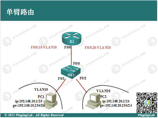
实验拓扑:
实验步骤:
1、依据图中拓扑,在SW1上创建VLAN,配置如下:
SW1#vlan database

SW1(vlan)#vlan 10 name VLAN_10

SW1(vlan)#vlan 20 name VLAN_20

SW1(vlan)#exit
将接口划入对应VLAN,配置如下:
SW1(config)#int f0/1

SW1(config-if)#switchport mode access

SW1(config-if)#switchport access vlan 10

SW1(config-if)#int f0/2

SW1(config-if)#switchport mode access

SW1(config-if)#switchport access vlan 20

SW1(config-if)#exit
2、根据拓扑为不同PC配置IP地址信息,如下:
PC1(config)#no ip routing

PC1(config)#int f0/0

PC2(config-if)#no sh

PC1(config-if)#ip address 192.168.10.1 255.255.255.0

PC1(config-if)#exit

PC1(config)#ip default-gateway 192.168.10.254

PC2(config)#no ip routing

PC2(config)#int f0/0

PC2(config-if)#no sh

PC2(config-if)#ip address 192.168.20.1 255.255.255.0

PC2(config-if)#exit

PC2(config)#ip default-gateway 192.168.20.254
3、将SW1与R1相连链路设置为Trunk链路,用于承载不同VLAN的流量,配置如下:
SW1(config)#int f0/0

SW1(config-if)#switchport trunk encapsulation dot1q

SW1(config-if)#switchport mode trunk

SW1(config-if)#exit
4、在R1上部署单臂路由技术,实现VLAN间通信,如下:
R1(config)#int f0/0

R1(config-if)#no shutdown

R1(config-if)#exit

R1(config)#int f0/0.10

R1(config-subif)#encapsulation dot1Q 10

R1(config-subif)#ip address 192.168.10.254 255.255.255.0

R1(config-subif)#exit

R1(config)#int f0/0.20

R1(config-subif)#encapsulation dot1Q 20

R1(config-subif)#ip address 192.168.20.254 255.255.255.0

R1(config-subif)#exit
5、测试单臂路由,如下:
①测试主机到网关的连通性
PC1#ping 192.168.10.254


Type escape sequence to abort.

Sending 5, 100-byte ICMP Echos to 192.168.10.254, timeout is 2 seconds:

!!!!!

Success rate is 100 percent (5/5), round-trip min/avg/max = 20/227/1036 ms
②测试主机与主机的连通性
PC1#ping 192.168.20.1


Type escape sequence to abort.

Sending 5, 100-byte ICMP Echos to 192.168.20.1, timeout is 2 seconds:

.!!!!

Success rate is 80 percent (4/5), round-trip min/avg/max = 24/48/84 ms
从上面可以看到,通过部署单臂路由技术,使得VLAN间的主机能够相互通信。此实验完成。
- 还没有人评论,欢迎说说您的想法!