
实验目的:
1、掌握帧中继的基本配置。
2、掌握通过路由器模拟帧中继交换机。
3、理解帧中继的映射表、转发表等。
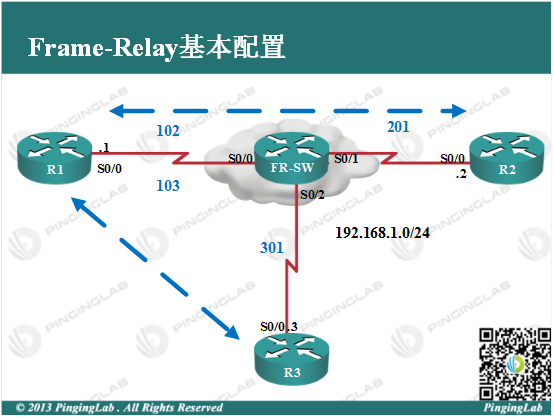
实验拓扑:
实验步骤:
1、依据图中拓扑,通过路由器模拟帧中继交换机,配置如下:
①开启帧中继交换功能
FW-SW(config)#frame-relay switching
②接口开启帧中继封装,并定义为DCE接口
FW-SW(config)#int s0/0

FW-SW(config-if)#no shutdown

FW-SW(config-if)#encapsulation frame-relay [PL2]

FW-SW(config-if)#frame-relay intf-type dce

FW-SW(config-if)#exit

FW-SW(config)#int s0/1

FW-SW(config-if)#no shutdown

FW-SW(config-if)#encapsulation frame-relay

FW-SW(config-if)#frame-relay intf-type dce

FW-SW(config-if)#exit

FW-SW(config)#int s0/2

FW-SW(config-if)#no shutdown

FW-SW(config-if)#encapsulation frame-relay

FW-SW(config-if)#frame-relay intf-type dce

FW-SW(config-if)#exit
③编写帧中继转发条目
FW-SW(config)#int s0/0

FW-SW(config-if)#frame-relay route 102 interface s0/1 201

FW-SW(config-if)#frame-relay route 201 interface s0/0 102

FW-SW(config-if)#exit

FW-SW(config)#int s0/1

FW-SW(config-if)#frame-relay route 201 interface s0/0 102

FW-SW(config-if)#exit

FW-SW(config)#int s0/2

FW-SW(config-if)#frame-relay route 301 interface s0/0 102

FW-SW(config-if)#exit
2、通过部署帧中继技术,使得各个站点可以互相连通,其中R1为中心点,R2和R3为分支点,配置如下:
R1上
R1(config)#int s0/0

R1(config-if)#no shutdown

R1(config-if)#encapsulation frame-relay

R1(config-if)#no frame-relay inverse-arp

R1(config-if)#frame-relay map ip 192.168.1.2 102 broadcast

R1(config-if)#frame-relay map ip 192.168.1.3 103 broadcast

R1(config-if)#exit
R2上
R2(config)#int s0/0

R2(config-if)#no shutdown

R2(config-if)#encapsulation frame-relay

R2(config-if)#no frame-relay inverse-arp

R2(config-if)#frame-relay map ip 192.168.1.1 201 broadcast

R2(config-if)#exit
R3上
R3(config)#int s0/0

R3(config-if)#no shutdown

R3(config-if)#encapsulation frame-relay

R3(config-if)#no frame-relay inverse-arp

R3(config-if)#frame-relay map ip 192.168.1.1 301 broadcast

R3(config-if)#exit
3、查看帧中继运行状态,如下:
①查看PVC状态
R1#show frame-relay pvc


PVC Statistics for interface Serial0/0 (Frame Relay DTE)


              Active     Inactive      Deleted       Static

  Local          2            0            0            0

  Switched       0            0            0            0

  Unused         0            0            0            0


DLCI = 102, DLCI USAGE = LOCAL, PVC STATUS = ACTIVE, INTERFACE = Serial0/0


  input pkts 89            output pkts 47           in bytes 8364

  out bytes 6032           dropped pkts 0           in pkts dropped 0

  out pkts dropped 0                out bytes dropped 0

  in FECN pkts 0           in BECN pkts 0           out FECN pkts 0

  out BECN pkts 0          in DE pkts 0             out DE pkts 0

  out bcast pkts 47        out bcast bytes 6032

  5 minute input rate 0 bits/sec, 0 packets/sec

  5 minute output rate 0 bits/sec, 0 packets/sec

  pvc create time 00:45:16, last time pvc status changed 00:18:37


DLCI = 103, DLCI USAGE = LOCAL, PVC STATUS = ACTIVE, INTERFACE = Serial0/0


  input pkts 0             output pkts 10           in bytes 0

  out bytes 1100           dropped pkts 0           in pkts dropped 0

  out pkts dropped 0                out bytes dropped 0

  in FECN pkts 0           in BECN pkts 0           out FECN pkts 0

  out BECN pkts 0          in DE pkts 0             out DE pkts 0

  out bcast pkts 10        out bcast bytes 1100

  5 minute input rate 0 bits/sec, 0 packets/sec

  5 minute output rate 0 bits/sec, 0 packets/sec

  pvc create time 00:45:18, last time pvc status changed 00:01:58
PVC状态处于Active状态,说明PVC连接没有问题。
②查看帧中继映射信息,如下:
R1#show frame-relay map

Serial0/0 (up): ip 192.168.1.2 dlci 102(0x66,0x1860), static,

              broadcast,

              CISCO, status defined, active

Serial0/0 (up): ip 192.168.1.3 dlci 103(0x67,0x1870), static,

              broadcast,

              CISCO, status defined, active
可以看到,由于关闭IARP并且手工绑定DLCI与IP的映射,所以这里显示Static,并且处于Active状态,说明映射没有问题。
③查看帧中继交换机上的转发表,如下:
FW-SW#show frame-relay route

Input Intf      Input Dlci      Output Intf     Output Dlci     Status

Serial0/0       102             Serial0/1       201             active

Serial0/0       103             Serial0/2       301             active

Serial0/1       201             Serial0/0       102             active

Serial0/2       301             Serial0/0       102             active
4、测试连通性,如下:
R1#ping 192.168.1.2


Type escape sequence to abort.

Sending 5, 100-byte ICMP Echos to 192.168.1.2, timeout is 2 seconds:

!!!!!

Success rate is 100 percent (5/5), round-trip min/avg/max = 36/42/60 ms

R1#ping 192.168.1.3


Type escape sequence to abort.

Sending 5, 100-byte ICMP Echos to 192.168.1.3, timeout is 2 seconds:

!!!!!

Success rate is 100 percent (5/5), round-trip min/avg/max = 16/31/52 ms
以上说明总部和分支和连通性没有问题,测试下分支之间的连通性,如下:
R2#ping 192.168.1.3


Type escape sequence to abort.

Sending 5, 100-byte ICMP Echos to 192.168.1.3, timeout is 2 seconds:

.....

Success rate is 0 percent (0/5)
可以看到,分支之间没法相互通信,查看R2和R3的映射表,如下:
R2#show frame-relay map

Serial0/0 (up): ip 192.168.1.1 dlci 201(0xC9,0x3090), static,

              broadcast,

              CISCO, status defined, active

R3#show frame-relay map

Serial0/0 (up): ip 192.168.1.1 dlci 301(0x12D,0x48D0), static,

              broadcast,

              CISCO, status defined, active
由于分支之间没有到对方的映射信息,数据没法正常封装,需要加入分支对方的映射,如下:
R2(config)#int s0/0

R2(config-if)#frame-relay map ip 192.168.1.3 201 broadcast

R2(config-if)#exit

R3(config)#int s0/0

R3(config-if)#frame-relay map ip 192.168.1.2 301 broadcast

R3(config-if)#exit
再次查看映射表,如下:
R2#show frame-relay map

Serial0/0 (up): ip 192.168.1.1 dlci 201(0xC9,0x3090), static,

              broadcast,

              CISCO, status defined, active

Serial0/0 (up): ip 192.168.1.3 dlci 201(0xC9,0x3090), static,

              broadcast,

              CISCO, status defined, active

R3#show frame-relay map

Serial0/0 (up): ip 192.168.1.1 dlci 301(0x12D,0x48D0), static,

              broadcast,

              CISCO, status defined, active

Serial0/0 (up): ip 192.168.1.2 dlci 301(0x12D,0x48D0), static,

              broadcast,

              CISCO, status defined, active
再次测试分支之间的连通性,如下:
R2#ping 192.168.1.3


Type escape sequence to abort.

Sending 5, 100-byte ICMP Echos to 192.168.1.3, timeout is 2 seconds:

!!!!!

Success rate is 100 percent (5/5), round-trip min/avg/max = 44/68/96 ms
当加入映射后,分支正常通信!注意,星形拓扑中分支之间的数据需要经过中心点进行转发。此实验完成。
- 还没有人评论,欢迎说说您的想法!